

Generate diagrams from CLI
The syside viz commands generate SysML v2 diagrams from models.
Learn about:
Single element diagrams: turn any model element into a diagram with a single command
Model view diagrams: repeatable diagrams defined as views in the model
Multi-file models: render models that span many files and directories
CI automation: generate diagrams in pipelines
Before you start
Make sure Syside is installed and activated
Select or create a SysML v2 model (
.sysml) for generating diagrams
This guide uses Example models.
Hint
Structure model files into directories (e.g., folder per subsystem). syside viz
loads models recursively, so the directory structure can help control what appears
in the diagrams (see Multi-file models).
Single element diagrams
Any element of a model can be turned into a diagram:
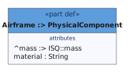
A single command generates the image above:
syside viz element DroneMissionModel.sysml --name "DroneMission::Components::Airframe" -o Airframe.svg
The diagram shows the element and everything it contains: owned elements like
capacity, and inherited ones like the ^mass attribute and the ^pwrOut port.
Hint
SysML v2 uses the ^ prefix to mark inherited elements in diagrams. Inherited
rows can be hidden per view with the showInheritedRows attribute, or globally with the
viz.compartments.show_inherited_rows configuration setting.
The --name argument selects the element to render: its qualified name becomes the
root node of the diagram. The argument can be repeated to draw several elements as root
nodes in one diagram.
The -o argument controls where the generated diagram is saved. It can be an absolute
path (e.g., C:\diagrams\Battery.png) or relative to the folder from which the
command is executed. Image format is derived from the output file extension, and can be
one of the following: svg, png, or jpeg.
Finding the qualified name
The qualified name is the path of names from the root to the element, joined with
::.
package DroneMission {
    package Structure {
        part def <QC> Quadcopter :> Drone {
            part powertrain : Subsystem;
        }
    }
}
Here, the full qualified name of powertrain is
DroneMission::Structure::Quadcopter::powertrain.
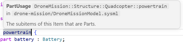
Names with spaces or special characters are quoted in SysML, and the quotes are part of
the qualified name: DroneMission::Interactions::MissionHandshake::'Ground Station'.
Wrap such names in double quotes for the shell:
syside viz element drone-mission/ --name "DroneMission::Interactions::MissionHandshake::'Ground Station'"
If no element matches, the command lists the closest matching names. Only the passed
files are searched, so a standard library name such as ISQ is not found.
The element must also draw as a node, so a dependency relationship, which draws as a line, is rejected.
Customizing presentation
By default, an element renders as a general view, in the nested style, with full depth. Each of these defaults can be changed from the command line.
syside viz element drone-mission/ --name "DroneMission::Components::Drone" --render tree --depth 2 --output-file Drone_tree.svg
The --view argument selects another view kind, such as interconnection or state_transition.
The --render tree argument draws the decomposition as a tree instead of nesting
children.
The --depth argument limits how many levels of descendants appear.
Warning
Argument parser rejects a bare -d -1 flag. For infinite depth, use the expanded
form: --depth=-1.
Default configuration
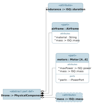
Custom styling with --config syside.toml
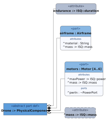
The command line covers the basics. The rest of the presentation, such as color customization, filtering and compartment visibility, is configurable through SysML views or a configuration file:
[viz.style.group.part_usage]
members          = ["PartUsage"]
fill_header      = "#88b7e3ff"
fill_body        = "#f7f9ffff"
text_keyword     = "#1f4373ff"

[viz.style.group.part_definition]
members          = ["PartDefinition"]
fill_header      = "#5d9ddbff"
fill_body        = "#f7f9ffff"
text_keyword     = "#163366ff"

[viz.style.group.attribute_usage]
members          = ["AttributeUsage"]
fill_header      = "#b1bcd0ff"
fill_body        = "#f7f8fbff"
text_keyword     = "#363f55ff"
The configuration can be passed to syside viz with the --config flag:
syside viz element drone-mission/ --name "DroneMission::Components::Drone" --render tree --depth 2 --config syside.toml --output-file Drone_styled.svg
For every flag and default, see the viz element reference. For every configuration setting, see the viz configuration reference. Groups can also select elements by the metadata they carry, see coloring by metadata.
Attribute presentation
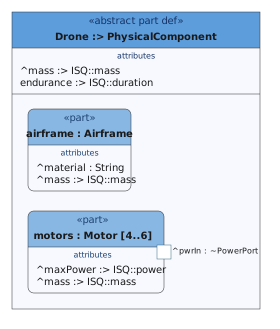
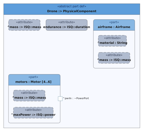
By default, attributes appear as compartment rows in the nested layout and as nodes in
the tree layout. show_attributes_as overrides this per view kind: "nodes" draws
each attribute as a box inside its owner, "compartments" keeps them as rows, and
"hidden" leaves them out.
show_attributes_as = "compartments"
show_attributes_as = "nodes"
show_inherited_nodes and the other [viz.filters.<kind>] settings are listed in the
viz configuration reference.
Model view diagrams
SysML v2 makes diagrams part of the model itself. Views, written in the same standardized language, select the content, the view kind, and the output file of each diagram. With the model as the single source of truth, the same command reproduces the same diagrams for everyone. This is the recommended approach for repeatable, version-controlled diagram generation. See Configure diagram views for defining views and finetuning their output.
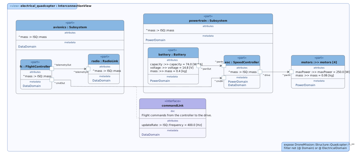
view electrical_quadcopter : InterconnectionView {
    expose DroneMission::Structure::Quadcopter::*::**;
    filter not (@ Domain) or @ ElectricalDomain;

    attribute fileName = "01_electrical_quadcopter";
}
The following command renders every view found in the model into the diagrams
directory, one image per view:
syside viz view drone-mission/ --output-dir diagrams
Warning
Views must be named to render: anonymous views are skipped with a warning.
Selecting views
The --name argument limits rendering to views at or under a qualified name. The
argument accepts both views and packages: the qualified name of a view renders that one
diagram, while the qualified name of a package renders every view under the package:
syside viz view drone-mission/ --format png --output-dir diagrams --name DroneMissionDiagrams::electrical_quadcopter
Customizing output
Output can be configured in two places: on the command line, applicable for a single
run, and in the model, for each view. On the command line, --output-dir selects
where the diagrams are written (default: ./output), and --format sets the image
format for all views at once.
In the model, each view carries its own configuration as regular SysML v2 attributes:
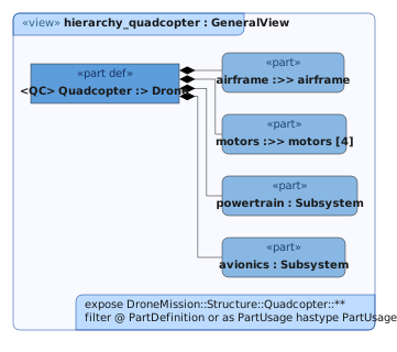
view hierarchy_quadcopter : GeneralView {
    expose DroneMission::Structure::Quadcopter::**;
    filter @ PartDefinition or as PartUsage hastype PartUsage;

    attribute depth = 2;
    attribute maxCompartmentEntries = 0;
    attribute showAnnotationRows = false;
    attribute fileName = "07_hierarchy_quadcopter";
    render asTreeDiagram;
}
This view renders as a two-level deep tree into 07_hierarchy_quadcopter.svg. A view
without a fileName is written as diagram-<view name>. See Configurable attributes for all available customization options.
Styling works the same as for single element diagrams, using the --config flag to pass a configuration
file.
Note
With three places to define a setting, conflicts are resolved by a fixed order of precedence: command-line arguments win over view
attributes, and view attributes win over the configuration file (e.g., a view’s
fileType attribute beats the configured format, but --format beats both).
See the viz view reference for a full list of available arguments and default values.
Connections with contents
By default, a connection that owns attributes, documentation, or other elements is
drawn with an elaboration node, a box attached to the line that holds them. The
commandLink interface in the electrical_quadcopter view has one for its
documentation comment and updateRate attribute.
Elaboration nodes can be hidden by showConnectionElaborations = false. This
draws all connections as plain edges with labels:
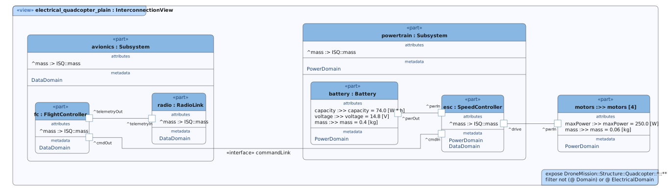
The same switch exists per view kind as viz.filters.<kind>.show_connection_elaborations configurable setting.
Coloring by metadata
A style group can select elements by the metadata they carry instead of by their type.
The drone model tags every electrical part, port and connection with its domain, @PWR
or @DATA, so one group per domain colors the whole electrical view by meaning: boxes
through the node settings, ports through the port settings, and lines through the edge
settings.
[viz.style.group.power]
members          = ["#PowerDomain"]
# -- Nodes -------------------------
fill_header      = "#f3cc7aff"
fill_body        = "#fdfaeeff"
text_keyword     = "#6e4f0dff"
# -- Edges -------------------------
stroke_edge      = "#a02020ff"
text_edge        = "#a02020ff"
# -- Ports -------------------------
fill_port        = "#f0a8a0ff"
stroke_port      = "#a02020ff"
text_port        = "#a02020ff"

[viz.style.group.data]
members          = ["#DataDomain"]
# -- Nodes -------------------------
fill_header      = "#80bbd6"
fill_body        = "#f4f9fc"
text_keyword     = "#1d465e"
# -- Edges -------------------------
stroke_edge      = "#2022a3ff"
text_edge        = "#2022a3ff"
# -- Ports -------------------------
fill_port        = "#b9c9ffff"
stroke_port      = "#2022a3ff"
text_port        = "#2022a3ff"
syside viz view drone-mission/ --config drone-mission/domains.toml --output-dir diagrams --name DroneMissionDiagrams::electrical_quadcopter
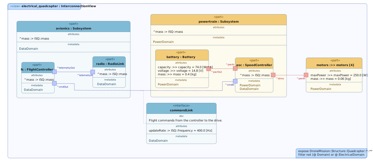
Power runs from the battery through the speed controller to the motors, and data from
the flight controller to the radio and to the speed controller. The speed controller
carries both tags. Groups that match equally well apply in declaration order, so the
later data group colors its box. Its ports are tagged one at a time, so drive and
pwrIn stay in the power colors while cmdIn takes the data ones.
See Select by metadata for name matching and
conditions, and Group precedence for which
group wins when several match.
Expose modes
A view’s exposeMode attribute decides how the elements its filter lets through map
onto the diagram, and exposeMode explained
walks through each mode with an example. On the command line it can also be set per run
with --expose, or globally with the viz.expose.mode
configuration setting.
Multi-file models
Models that span several files render the same way: pass the directories, and every
.sysml and .kerml file inside is collected recursively. Paths can be files,
directories, or glob patterns, mixed freely; overlapping paths are collected only once.
File discovery follows the same rules as syside check.
syside viz view drone-mission/DroneMissionModel.sysml drone-mission/DroneMissionViews.sysml --format svg --output-dir diagrams
Passing only part of a model breaks its references to the files left out. Each broken
reference is reported as a reference-error naming the missing namespace, and no
diagrams are produced until all references resolve.
Hint
If parts of the model live outside the passed directories, such as an external
library or a shared package, add their locations with --include. Included paths
join the positional paths in file discovery, so views found there render like any
other:
syside viz view drone-mission/ --include lib/ --format svg --output-dir diagrams
Excluding files
In larger repositories, passing whole directories quickly collects more than intended.
Validation runs on everything collected, so a single broken work-in-progress file aborts
rendering for every stable model in the tree. The --exclude argument removes files
or glob patterns from discovery:
syside viz view models/ --exclude "models/sandbox/**" --format svg --output-dir diagrams
Duplicate copies of a model are a quieter trap. When two collected files declare the same top-level element (e.g., a stable model and its archived copy), the copies shadow each other in the global namespace.
Warning
The CLI treats duplicate namespaces as warnings, not errors. They are reported, but do not prevent the CLI from generating diagrams. This can lead to unexpected non-deterministic behavior.
Exclude duplicate files when any such warnings appear.
For a model that always needs the same locations, set include and exclude in the
syside.toml file instead of repeating the flags. See
Configure the extension for details.
CI automation
Diagram generation is fully headless: syside viz can run on any CI runner or
container where the CLI is installed and activated.
Runners can be licensed with a deployment key kept in the CI provider’s secret storage
(see Install the Python Library & CLI), or, for air-gapped setups, with a license file
(see Offline license).
A typical pipeline job validates first, then renders:
syside check
syside viz view models/ --format svg --output-dir diagrams
Validating separately turns model errors into a validation failure with full diagnostics instead of an aborted render. A failed step exits with a non-zero code, which fails the pipeline (see exit codes). The output directory can be published as a pipeline artifact for review.
A shared syside.toml in the repository gives the pipeline and engineers’ machines
the same render settings. The CLI discovers the
file automatically, and --config selects one explicitly.
Renders are reproducible: the same model, configuration, and CLI version produce identical files.
Pin the CLI version used by the pipeline, as diagram output may change between releases.
Example models
The drone mission model is a small, complete example for trying the commands on this page. It contains eleven defined views.