

Configure diagram views
SysML v2 diagram views let you define which elements to include in a diagram and how to render them, with additional diagram customization through configurable attributes.
package MyViews {
    private import Views::asTreeDiagram;

    part def SystemViews {
        view customDroneView {
            expose DroneMission::Structure::Quadcopter;
            filter @ SysML::PartUsage;

            attribute depth = 2;
            render asTreeDiagram;
        }
    }
}
This view exposes the Quadcopter element and filters its contents to show only
elements which have metadata of type SysML::PartUsage. The view also contains
attribute depth, which tells Syside how deep to traverse each subtree, and render asTreeDiagram which tells Syside which rendering style to use. This page covers the
view kind and the configurable attributes in detail. For expose and filter, which decide
which elements reach the diagram at all, see Select diagram elements.
Choosing the view kind
The SysML v2 specification defines eight standard view definitions, available through
the standard library package StandardViewDefinitions. Typing a view by one of them
selects the kind of diagram it produces:
package MyDiagrams {
    private import StandardViewDefinitions::*;

    view partWiring : InterconnectionView {
        expose MySystem::powertrain::**;
    }
    view chargingStates : StateTransitionView {
        expose MySystem::modes::**;
    }
}
Syside supports the following kinds as diagrams (see SysML v2 diagram coverage for examples):
View definition |
View kind |
|---|---|
|
General (structure, containment, and relationships) |
|
Interconnection (parts wired through ports) |
|
Action flow (actions and control flow) |
|
State transition (states and transitions) |
|
Sequence (lifelines and messages) |
Note
An untyped or unrecognized view renders as a General view. As an alternative to
typing, a render asInterconnectionDiagram; statement selects the interconnection
kind.
Configurable attributes
The following attributes control how each view renders.
Attribute |
Default |
Since |
Description |
|---|---|---|---|
|
|
0.10.0 |
How many levels of descendants to show. |
|
Nested Diagram |
0.10.0 |
Layout style. Use |
|
|
0.10.0 |
Output format: |
|
|
0.10.0 |
Output file name. |
|
|
0.10.0 |
Zoom level for rendering. Applicable only to PNG and JPEG output. |
|
|
0.10.0 |
How the view’s filters interact with exposed elements: |
|
|
0.10.3 |
Per-compartment row cap: |
|
|
0.10.3 |
Hides inherited ( |
|
|
0.10.0 |
Hides annotation (documentation and metadata) compartment rows when set to
|
|
|
0.11.0 |
Draws all connections as edges when set to |
|
|
1.0.0 |
Hides types, specializations and multiplicities in declarations when set to
|
|
|
1.0.0 |
Hides values (i.e. content after |
The fileType and fileName attributes name an output file, which the panel does not
write on its own: its save dialog asks for a file
name and takes the format from its extension.
Note
Except for render, which comes from the standard Views library, these
attributes are Syside-specific and have no effect in other tools.
An attribute set on the view takes precedence over the matching
[viz] setting in syside.toml.
depth explained
depth controls how many levels of each exposed element’s subtree to traverse.
Traversal happens after filtering, so the diagram may include element types that
were filtered out. To avoid this, set depth to 0 or 1 when using filters.
0 shows only the filtered elements. Because filtering applies to elements rather
than relationships, no relationships between them appear at this depth.
1 shows the filtered elements and the relationships between them: ownership, state
transitions, connections, and similar. Use this depth when relationships need to be
visible.
-1 (the default) means infinite depth, which is useful for exploratory diagrams but
typically too detailed for documentation and may contain elements that should be
filtered out.
render explained
render controls the layout style used to display the diagram. The default Nested
style shows child elements inside their parents; Tree arranges them as a branching
tree instead.
To switch to Tree layout, add a render Views::asTreeDiagram; statement to the view.
For a single element, the layout can also be picked in the panel with the
Layout picker, without changing the model.
exposeMode explained
In SysML v2, a view exposes a portion of the model and filters it down to a flat list of exposed elements: the elements allowed to appear in the output. For textual output, that list is the final answer. A diagram, however, has to map the exposed elements back onto the containment hierarchy, and the mapping becomes ambiguous as soon as an element passes the filter while its parent does not. The expose mode selects the mapping strategy.
The drone mission example model runs into this with its medical delivery variant. The medkit is cargo, not a component of the drone, so it is modeled as an item:
part def MedicalQuadcopter :> Quadcopter {
    item medkit {
        part sampleCooler : SampleCooler { @ELEC; }
        part trackingBeacon : TrackingBeacon { @ELEC; }
    }
}
Each mode resolves the conflict differently:
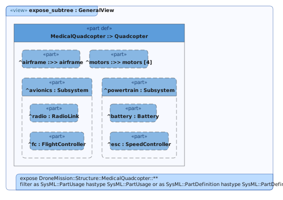
The default mode. A filtered element is dropped together with its whole subtree:
the medkit takes sampleCooler and trackingBeacon with it.
Useful for pruning the architecture cleanly.
view expose_subtree : GeneralView {
    expose DroneMission::Structure::MedicalQuadcopter::**;
    filter (
        as SysML::PartUsage hastype SysML::PartUsage or
        as SysML::PartDefinition hastype SysML::PartDefinition
    );
    attribute exposeMode = "subtree";
    attribute fileName = "08_expose_subtree";
}
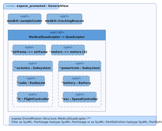
Filtered elements are dropped, but their exposed descendants are promoted to the
view frame, titled with their path from the exposed element
(medkit::sampleCooler). Nothing the filter allows is lost.
Useful in cases where the diagram must account for every exposed element.
view expose_promoted : GeneralView {
    expose DroneMission::Structure::MedicalQuadcopter::**;
    filter (
        as SysML::PartUsage hastype SysML::PartUsage or
        as SysML::PartDefinition hastype SysML::PartDefinition
    );
    attribute exposeMode = "promoted";
    attribute fileName = "09_expose_promoted";
}
Containment is not reconstructed at all: every exposed element renders as an independent sibling, titled with its path from the exposed element. Inherited members become siblings too. This is the flat list shown literally.
Useful for inventories and catalogs.
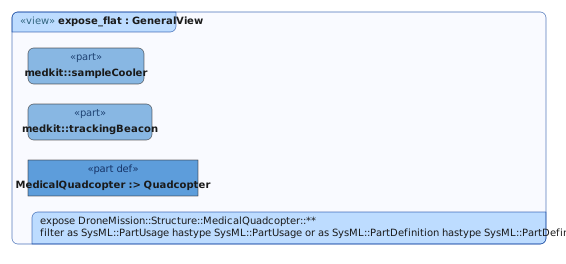
The example model changes the mode using the exposeMode attribute. The
viz.expose.mode setting sets it for every view that
does not.
Common pitfalls
The following behaviors are correct but regularly surprise view authors.
View name becomes diagram frame title
The view name is not an internal identifier: it renders verbatim as the diagram title in
the frame, so a view named 05_power_distribution shows that 05_ to every reader,
in a diagram panel as much as in a saved file. Keep ordering prefixes out of view
names, and give the file its name in the save dialog instead.
depth demotes elements instead of hiding them
Elements beyond the depth limit collapse into compartment rows of their parent. Relationship edges that target a demoted element (verify, satisfy, allocate, and similar) cannot render as arrows and surface as textual compartment entries instead.
To keep relationship arrows, keep both endpoints within the depth limit, or leave the depth unlimited.
Relationship edges need both endpoints as nodes
If one end of a keyword relationship is absent or demoted to a compartment row, the edge disappears or degrades to text.
Example model
The drone mission model used on this page is a small, complete example with eleven defined views. Open its folder in VS Code and visualize any of them.